
Chapters 1 – 5 bring us up to date with the coding side of the matrix project… all the POC work is done and most of the components are built to some extent. There are 2 main challenges remaining:
- Adding functionality to ex:bit so that it can be used to specify a node / row / column in the matrix and send an image / animation to it. This requires extending ex:bit and building a (micro:bit) server to take this data (over UART) and convert it into radio instructions the matrix nodes can understand.
- Building a UI to specify the UID on each node (to bypass having to hardcode it). I have a great idea that means minimal effort for the user – fitting it onto the already chockers node code is going to be fun!
But all that code is useless without a real-world matrix to project onto – ergo I need some kind of physical superstructure to hold the individual micro:bits…
Building the physical matrix
A micro:bit matrix has to be a rectangular grouping of multiple micro:bits that stands upright, right? Put it this way, flat on the ground is definitely not an option. To stand upright requires some kind of scaffold / container – in principle not too hard I guess, but there is a key constraint to consider:
The matrix code does not limit the size / shape of the matrix, so the physical build MUST include this flexibility too. A rigid and fixed housing with a constant number of rows / columns for the matrix is not an option.
So I set out to design a system that would allow me to take a pile of micro:bits and put them into different physical (rectangular) shapes without too much hassle. I was looking for a solution that met the flexibility constraint as well as the following::
- Low cost.
- Something I could build myself from upcycled parts.
- Easy to make.
- Form factor had to be OK – I wasn’t concerned about aesthetics, but it couldn’t look too ugly.
- The gaps between adjacent micro:bits must be minimal – see the end of this chapter for more on this.
- Each housing is self-contained. This means it needs to encompass the battery too.
I decided to try and build a housing for each individual micro:bit – one that could be attached to others – I had Lego in mind.
I will spare you the full journey and skip to the solution, but during that journey I stumbled across the following key observation:
I planned to use pieces of louvre that would lay flat on the micro:bit. I discovered that the back of the micro:bit is far from flat though – components, solder and test points give the reverse of the board an irregular profile.
The diagram below shows a couple of ‘clear tracks’: areas on the board where there are no protuberances:
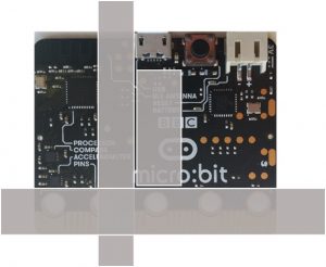
The shaded grey areas are the ‘smooth’ parts on the reverse side of the micro:bit. In other words, they are the areas where you can lie a flat piece of material flush with the surface.
Once I had this information in hand the solution pretty much designed itself!
The Components:
There are a handful of components that make up the housing:
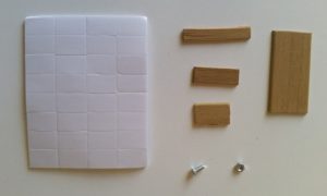
- The 4 bits of wood are cuts from a louvre and are carefully sized (tolerances are limited).
- The screw is used to attach the housing to the micro:bit
- The double-sided sticky pads are used to attach the battery pack to the housing.
Putting the components together:
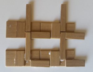
I used wood glue to connect the pieces together as shown below:
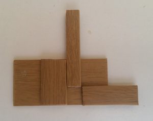
Note how this shape is almost a mirror image of the diagram above – the one that showed the smooth parts on the back of a micro:bit. FYI it is the 3 pieces in the foreground that sit flush against the back of the micro:bit. One of my lads pointed out it looks a bit like the middle finger salute! Kids, hey! Still, once you’ve seen it its pretty hard to un-see 😉
Connecting it to a micro:bit
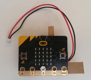
A single screw, through pin2, connects the housing to a micro:bit:
Be very careful in making the screw-hole. Louvre wood is very easy to work, but will split if not handled with care. Using a bradel is almost guaranteed to split the wood. I used a very find drill bit to make a pilot hole, then a larger one to get it to size, and that worked fine.
From the back it looks like this:
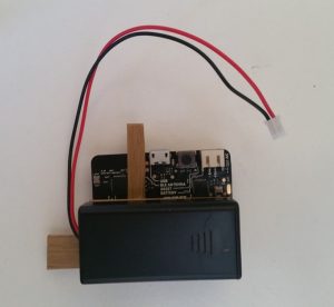
The battery is placed so that the bottom is in line with the bottom of the board, which allows the micro:bit to sit upright on a flat surface.
The cable is a bit annoying! Its really important to have minimal gaps, but the cable increases the gaps between adjacent micro:bits in 2 ways:
- On the side it comes straight out of the battery holder – this collides with the battery holder on the adjacent micro:bit, increasing the horizontal gap.
- On the top it is plugged into the JXT connector and impacts the bottom of the housing of the micro:bit above it. An incision into the wood takes care of most of this.
On the whole the battery pack / cable is the weak point in the design – in particular because it makes columns top-heavy.
Connecting the micro:bits together:
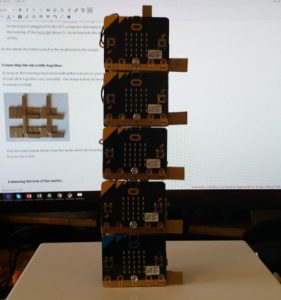
As long as the housings have been built within tolerances your micro:bits should all fit together very smoothly. The image below shows how the housings overlap:
The image above also shows how small differences in the shape of the housing result in a wonky superstructure, pointing to a weakness in the manufacturing process.
Even with these manufacturing flaws you can stack as many as 5 micro:bits free-standing on a flat surface (any more than that and the battery packs cause the column to topple):
The video below shows how the housing can be used to build upwards and sideways:
The vid shows the POC for stackable #microbit ‘cases’.
These can be joined to make a free-standing physical matrix of variable dimensions, a key element of my epic matrix project.
More details here: https://t.co/VVaflbwnVn
And why the giraffe? https://t.co/sYO6jg3syl pic.twitter.com/IK1MVR2jDj— Philip Meitiner (@pragmaticPhil) April 8, 2018
What I learned from the POC:
- The design is fit for purpose – it works.
- Making the housings with louvre will not scale. I need a higher precision method. Small deviations from the ideal cause weakness over a larger structure. Any ideas for how to manufacture these would be appreciated.
- Something else needs to be done with the battery pack. A coin cell would do the trick of course, but who says the battery pack HAS to be attached to the micro:bit? The idea of a separate but similar modular system for battery packs is stirring.
Enhancing the look of the matrix:
Once built there is another challenge I will need to address: in testing on smaller matrices I observed that…
… each screen is necessarily relatively far apart – the horizontal gaps between each screen are bigger than the screen itself. For smaller matrices this impacts on images transitioning between screens. The effect we are trying for – the matrix being a single monitor – is impacted significantly.
The 1000 micro:bit matrix does not suffer from this though. This is because people typically stand quite far back from it when watching it. The radiance of the LEDS diffuses over distance I guess, and the whole matrix can be seen as a single screen. Standing far enough back from it you hardly notice the gaps.
I have it in mind to try and find a transparent material that diffuses light. I’ll drape this over the front of the matrix and it will cause pixels to bleed a bit, reducing the ratio of gap to screen as perceived by the viewer. I think a cut of high transparency Perspex (pedant note – to say ‘sheet of Perspex’ is redundant – Perspex is a TM for acrylic sheets of polymethyl methacrylate) might do the trick. Once I have a prototype I’ll use trial and error to find a suitable solution.
In conclusion:
I will finish this some time – it has fun potential and I’ve gone too far now not to! I only have a few micro:bits lying around though, so its unlikely I’ll ever make a matrix large enough for Tetris (but I can borrow from local buddies and of course the library, so who knows!). Now that I am not working for micro:bit finding the time is a bit more challenging, but it will get finished, eventually.
Watch up for updates, which I will post on twitter (I tweet as @PragmaticPhil).
The micro:bit matrix saga currently consists of 6 chapters:
- The micro:bit matrix
- The micro:bit matrix (2) – design
- The micro:bit matrix (3) – nodes
- The micro:bit matrix (4) – ex:bit
- The micro:bit matrix (5) – Tetris
- The micro:bit matrix (6) – structure