Have you ever lamented the limited range of user-triggerable events that can be used as an input mechanism for the micro:bit? There is only so much you can do with 2 buttons and an accelerometer!
The Philtronic2000 (PT2) was originally conceived as a controller for the micro:bit house. I built it to give me a much broader range of input options than the micro:bit has natively.
If I am completely frank I also did it cos I imagined a wooden controller that looked a bit steam-punk – the sort of thing that would not look out of place in the lair of a 60s James Bond villain! It didn’t come out like that, but I was not unhappy with the (unfinished) product:
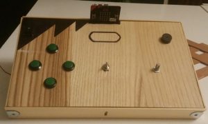
User input widgets:
It has 4 momentary buttons, a toggle button, an on/off switch (top left) a potentiometer and a piezo buzzer.
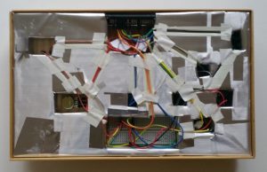
These are all connected by jumper cables to a breadboard, which is then connected to the micro:bit via an edge connector. Both the breadboard and the edge connector are inside the guts of the box (see below). The case has an integrated edge connector which the micro:bit you can see in the pic above plugs into.
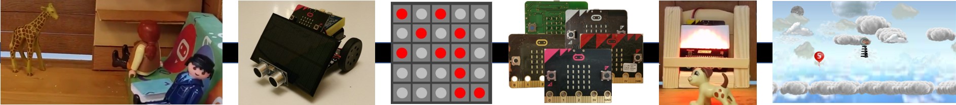
The idea is that the events triggered by the user are communicated to the micro:bit, which then transmits information about them over radio to a listening device. I’ve used the PT2 on my model house and my matrix, and I am sure it will get used in any other projects I might take on.
Construction:
The top is a piece of veneer wood – it was the back part of a cupboard. Thin, easy to work, light and good looking (I love wood!) – I am seriously at risk these days of choosing new furniture based on its upcycling potential!
The sides are the wooden louvres from a blind – my go-to construction material! They are held together by cheap braces bought from the local DIY shop.
The bottom is a mesh made from louvres – it holds the insides in whilst having enough gaps to allow someone to see the insides, if they were inclined to do so.
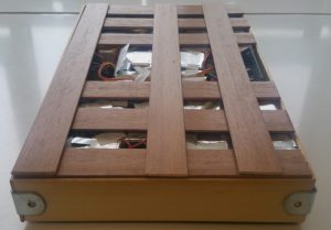
Inside it’s polystyrene all the way, chiselled and shaped to channel the cables neatly to where they need to go. The channels in the polystyrene are covered with stickers – last thing I wanted was a short causing poisonous polystyrene fumes to ruin whatever event I was using it at!
Sundries:
- Sadly the PT2 remains unfinished. The on/off switch in the top left never worked due to dodgy soldering, but this didn’t impact on its usefulness! I also wanted to put 2 LED ‘eyes’ in the oval that would light up when it was powered up and would change colour depending on the widget used. One day maybe!
- The ratio of edge to width is of course the golden ratio – in case you were wondering why it wasn’t similar to the micro:bit dimensions.
- The pattern on the front (the ‘fringe’, as it is called in micro:bit circles) is drawn in with a Sharpie. There is some bleeding along the edges, but you have to get pretty close to see it, and you’d have to be pretty pedantic to mention it!
- The 4 green momentary buttons form a perfectly spaced rhombus… but the positioning just looks wrong. I should have shrunk the proportions in line with the shape of the PT2. That still bugs me now, but hindsight is 20-20, as they say!