As detailed in chapter 1, to read all the info off the keypad I needed 8 analogue pins. There are only 6 on a micro:bit though, so my solution required 2 micro:bits.
At first that was a real buzz kill – it seemed way too OTT a route to go down and I put down my keyboard and gave up. But I really wanted to see that keypad working and found myself gravitating back to the project a day or two later.
In the end it turned out I actually needed to use 3 micro:bits:
The micro:bit has 6 pins that can perform an analogue read: 3 are ‘touch pins‘ (pin0, pin1 and pin2) and the other 3 are ‘analogue pins‘ that are also connected to the screen. This means that any activity on the screen impacts on the analogue reading for the 3 analogue pins, and THIS INCLUDES LIGHT LEVELS IN THE ROOM! In testing I found using the screen would prevent the associated pin from working predictably. To use the analogue pins to monitor for keypad button press events I would have to disable the screen on the 2 micro:bits I used to read the pins.
This means using a third micro:bit as a VDU.
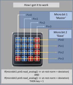
The 2 micro:bits used to read the keypad are connected as shown below:

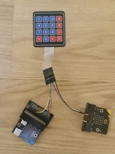
Which looks quite inelegant in the real world:

The micro:bit on the left above is the ‘Master’, and it is connected to the 4 columns. The one on the right is the ‘Slave’ and reads the rows. Both use the same code, but each has a hardcoded global param indicating which type they are.
Note: A key-press event is recorded when the analogue reading on one AND ONLY ONE pin is greater or less than the threshold (chapter 3 goes into a lot more detail about these thresholds). This means that if the Slave or Master record activity on 2 or more pins simultaneously it is ignored.
From the moment a key has been pressed the process progresses as detailed below:
- When the Slave records a key-press event it sends info about the event over radio.
- When the Master records a key-press event it monitors the radio waves to see if a similar event has been recorded by the Slave.
- The Slave sends the info over radio a few times per event – 10 times in a 250ms period. During that period it does not monitor activity on its pins.
- The Master waits 250ms after a key press event to see if an event from the Slave is being broadcast. It too stops monitoring its pins during this period.
- Where the Master has recorded an event on its own pins, and has received details about an event on the Slave, it will compile the 2 pieces of information to infer which one of the 16 keys has been pressed.
- The Master will compose this information into a string, which it sends over the radio to the third micro:bit, which is acting as the visual output device / screen.
- The micro:bit serving as a screen monitors constantly for radio messages (which means that it has to ignore the messages sent by the Slave). When a legitimate message (from the Master) is received it displays the associated key.
- After the screen has processed a legit message it chills for 250ms and clears out its radio queue.
Now that all sounds relatively simple (albeit convoluted) and it is. I have stated elsewhere that I found it very difficult to get this working though. The most significant challenge was in optimising the analogue thresholds (the analogue readings at which the system would infer a key-press event has occurred). I’ll go into more detail on that in the next chapter.
Next: The micro:bit calculator (3) – (currently WiP)
